Wednesday, April 6, 2016

Part 5 - Navisworks - Dealing with Objects

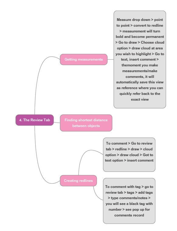
Below is the mindmap of Part 5 - Naviswork - Dealing with objects
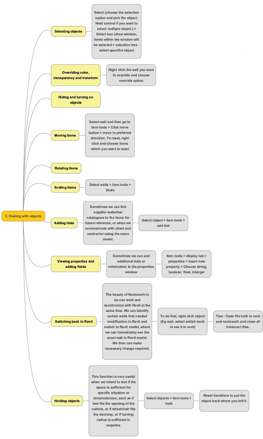


1. Selecting object

1. Select (choose the select option and pick the object). Hold control if you want to select multiple object.
2. Select Box (Draw a window, items within the window will be selected)
3. Selection Tree – select specific object


2. Overriding colour, transparency and transform
Right click the wall you want to override and choose override option


3. Moving items

Select walls and then go to item tools > Click move button > move to preferred direction.
To reset , right click and choose items which you want to reset. 

4. Scaling items
Select walls > item tools > scale

5.Adding link
Sometimes we can link supplier websites / catalogues to the items for future reference, or when we communicate with client and contractor using the same model.

Select object > item tools > add link


6. View properties and adding fields
Sometimes we can add additional data or information to the properties window.
Item tools > display tab > properties > insert new property > choose string, Boolean, float, interger


7. Switchback function
The beauty of Naviswork is we can work and synchronise with Revit at the same time. We can identify certain walls that needed modification in Revit and switch to Revit model, where we can immediately see the exact wall in Revit model. We then can make necessary change required.
To do that, we can right click object (eg wall, select switchback to see it in revit).
Tips : Open file both in revit and naviswork and close all irrelevant files. 

8. Holding objects
This function is very useful when we intend to test if the space is sufficient for specific situation or circumstances, such as if bed fits the opening of the cubicle, or if wheelchair fits the doorway, or if turning radius is sufficient in carparks.
Select objects > item tools > hold
Reset transform to put the object back where you left it.  

6. Sorting and Grouping
Right click item > selection inspector > pop up window with selection inspector


Part 4 - Naviswork - The Review Tab

Below is the zoom in mindmap on part 4 of Naviswork - The review Tab

Getting measurement
1) Measure drop down >  point to point > convert to redline > measurement will turn bold and become permanent


Creating Redlines
1)      To comment > go to review tab > redline > draw > cloud option > draw cloud > Go to text option > insert comment

2)      To comment with tag > go to review tab > tags > add tags > type comments/notes > you will see a black tag with number > see pop up below for comments record.


To find out characteristic of walls, right click to select wall to see wall description (item name/item type) 


Tuesday, April 5, 2016

Part 3 - Naviswork - How to work with viewpoints in Navisworks ?

Below is the zoom in mindmap on part three of Naviswork - Working with viewpoints 

Saving a viewpoint
Viewpoint > save viewpoint > rename viewpoint


Choosing render style
Viewpoint > render style > mode > full render/shaded/wireframe/hiddenline


Changing the background
1) Plain background colour
View > scene view > background > plain > change the colour

2) Horizon sky colour
View > Scene view > background > mode –Horizon > mix the colour you want


Slicing model using sectioning
(i) Plane section

Viewpoint > enable sectioning > transform > small arrow @ plane settings > link section planes > link front and top > hover cursor to the arrow, there will be a small black palm appearing, it will be yellow when activated.


(ii) Box section
Sectioning tools > mode > box > adjust section box to preferences

Part 2 : Navigating in a model -- How to navigate in a model ?

Below is the zoom in mindmap on part two of Naviswork - Navigate in a model


Looking around your model
Viewpoint > navigate > look at


Using Gravity Tool 
Viewpoint > render style > realism > check gravity 


Using View Cube
Right click view cube > choose option – set current view as home / - Set current view as front

Part 1 Naviswork file system - How to open files directly in Naviswork ?

Below is the zoom in mindmap on part one of Naviswork file system. It is pretty clear and self-explanatory. 

The practical part.
How to open files directly in Naviswork ?

Open > Click Open 

Monday, April 4, 2016

An Overview on Naviswork

A while ago, we have been doing some experimental studies on Navisworks. Naviswork is a 3D design review package for Microsoft Windows. Used primarily in constructoion industries alongside with Autodesk Revit, Autocad and Microstation, it allows users to open and combine 3d models, navigate them around in real-time and review the model using a set of tools, including comments, redlining, viewpoings, and measurements. There are also interesting and useful functions such as clash detection, 4dD time simulation. photorealistic rendering and PDF-like publishing.

In our office, we experimented and pilot a project using Naviswork in one of the project which I am handling -- a remodelling of an existing ward in a local hospital, Changi General Hospital, we used Naviswork to monitor on the sequence of constructions (due to site constraint and to shorten time needed for renovation), location of coring etc. Although the scale of the project is very small for Naviswork, it was a good exercise in getting our hands dirty, studying Naviswork as a tool for project management (which I would be sharing in another post).

The overall process / flow of work (in general, not in detail) in carrying out a project utilising various platform (AutoCad, Revit & Naviswork), in this case Ward 15 in Changi General Hospital are as below. There are several back and forthwork involved in Revit and Naviswork since both of this software can be synchronising at the same time and changes can be reflected almost immediately.
Click to View Larger

For now, I would like to share an overview mindmap of Naviswork, constructed as I was studying online via Lynda.com. The tutorials conducted by Eric Wing was amazing.

The mindmap is massive, considering there are many aspects to cover in Naviswork, but trust me, it is rewarding. For the subsequent blogpost, I will be breaking down the mindmaps into smaller mindmaps with screenshots on how I practiced using Naviswork in subsequent blogposts.


Disclaimer : tutorials posted here are just a record on how we practiced and experimented on the software. Please forgive/feedback if there is any error spotted as we are still baby steps in learning.

Friday, April 1, 2016

Changing Line Colour (Imitating AutoCad)

Our office Cad layer system uses certain color to define certain layer. For example, red for wall line, blue for accessories for line weight. Here are some simple ways to make line in Revit look AutoCad.


1. First, go to Visibility Graphic (shortcut key VV) > Model Categories , click on Object Style


2. Here you may change the Line Colour & Line Weight according to your preferences.


3.  Yup, Now you have a Edges Line Colour you wish for !


Thursday, March 31, 2016

Creating Visibility for void


Yesterday I was attempting to create a yes/no parameter for visual panel of the fire rated door, However, Revit doesn't have a visibility for void extrusion, there are a few methods I discovered in the internet, one of them can be found at Revit Nightmares Blog

which is simple to use the following formula
IF (<condition>, <result-if-true>, <result-if-false>)

I have posted the query on forum to find out more about the "Inconsistent Unit" Dialog, Apparently there are other methods to make it simpler, I will post more on my findings.


Using 1, and 0 with 1=1, and 1=2 (assuming 1 to equal true/on and 0 to equal false/off)

Will follow up again, once i figure out more about it.

To Show Datum Level on Axonometric


I was preparing an axonometric drawing which was to be shown to our client regarding the phasing of the building and the levels of the particular floors, which I used to do it in Sketchup (Fig 1)


(Fig 2 - the result i wish to create)


(Fig 1- SU Model)

However the 3d gridline in Revit 2016 does not allow me to create datum level (Fig 2) in Project , So I ended up using 3d Model Text to indicate the level, Alternatively, I could move it to Massing Environment, where the datum level can be shown.

Hopefully, the upcoming version of Revit would allow us the option to show datum level on axonometric in project environment.