Friday, May 20, 2016

How to switch of certain layers or elements in linked revit models ?

Generally, by default, everything that is in linked Revit models are reflected as it is. Sometimes, we would like to reflect or hide different info depending on type of submission. For example, in CBPU (Plumbing and Sanitary Submission), we only need to reflect the proposed or affected plumbing and sanitary points and not the escape route (ingress, egress routes) which are normally reflected in fire submission.


In this post, I am going to share on how to switch of certain layers or elements in linked Revit models.

1. Go to view ribbon > user interface > check properties. You will then see a properties pop up window. Under the properties window, go to identity data, under view template, click the view template itself. 

2. Under view template, go to V/G Overrides RVT Link. Click Edit.  


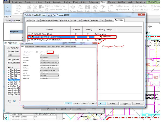
3. Under the linked Revit file, change display settings from "by host view" to "custom" as below : 

4. Go to the second tab (Model categories), change "<by host view> " to "<custom>". 
When it is "by host view" the details in the table are greyed out. No changes can be made. 

5. Once it is changed to "custom", the details in the table can be changed. Here is where we can start to switch on and off certain layers or elements in linked revit model. 

6. In our case, we would like to switch off egress and ingress path in the drawing since this is a sanitary submission. So under generic models, switch off "egress path, egress solid and hidden lines".


7. Now, the escape route in the linked model is switched off and the drawings only reflect details required for sanitary submission. 


Thursday, May 19, 2016

How to find out saved path or location of the linked autocad files in Revit ?

Sometimes, when having many autocad links in a Revit files and it comes to a point that we need to know where these links are stored. Ideally, they all should be stored systematically in a specific folder as below – a folder with linked autocad file created specifically for BIM.


In any case, to find out saved path or location of the linked files,  go to 

manage ribbon > manage link.


Under CAD format tab, you will see the saved path of each autocad file which are linked in the Revit model. Refer image below.

For items that is indicated as not found, you can either reload it again from the same folder (when revit file is moved and autocad files are still located in the same folder) or from different folder (when revit file remains the same path but autocad file is relocated to different folder or REMOVE it if it is not useful anymore.
 

Why do linked CAD files are unable to snap or move in REVIT, but only align?

Yesterday while i was working on linking an Autocad files in my revit model, I was unable to pick, snap or move any lines from the linked autocad file. It is pretty frustrating as all i could do to move the autocad file to the desired location is to align accordingly. :(

After researching, trial and errors and experiments, there is a solution to that, which i have recorded in the image below. The trick is to enable select link option when you want to be able to select linked files and individual elements in the links. I do not know whether it was disabled by default or not but at least now i have another place to check when I could not move or snap my linked autocad files.

Steps :
1. Click the imported linked cad files.
2. Enable select link option. (see image below)

Monday, May 16, 2016

How to create curve or angled mullion on regular curtain wall

Normally when creating  mullion, the limitation we cant have 2 angle when rotating the mullion angle. Here are some simple steps to create a curve or angled mullion combined with regular grid

1. First create architecture wall (curtain wall) with some mullion grid ,


 2. Selection the Curtain wall , duplicate it by copy to clipboard


  3. Paste the same curtain wall ,"with Align to Same Place" , there will be

 3.  There will be  some error message pop up, just ignore it , close out on it


 4. Click on the isolate element "sunglass icon at the very bottom"


 5. Select every click on filter, select only the grid mullion and grid and delete, (we have the mullion on the 1st curtain wall)


  6. Select the 2nd Curtain wall and click on edit type , Change the Curtain Panel = Empty System Panel: Empty. (to delete the glass , because the glass is already in the 1st Curtain Wall)


 7. Now the glass is deleted , while it is still selected , go ahead and click Edit Profile


  8. Edit your desire mullion angle or curve  (it required to be in a close shape)


 9. Dont worry if it white out, just move around to find the gridline , c


8. Click on mullion , and press on the angled grid to give mullion profile 


  9. Once completed , press on the sunglass to exit the temporary isolate


In usual case , revit don't automatically embed curtain wall if  there are both overlapping


 So when you draw a architectural wall overlapping with the existing curtain wall, error message will pop up, just ignore it


 then go to the elevation, select the 1st curtain wall and click on edit type , make sure it say automatically embed (with tick)


There you should get it properly cut out.


Source : https://www.youtube.com/watch?v=sUx7v_i9d-g